@peritoz/smart-view-engine v0.2.2
Smart View Engine
Advanced automatic layout generator for better graph visualization.
About
This lib was created after observing how hard it can be for some experts to communicate an architecture accurately. Architecture representation and visualization are part of the process of solution design. However, sometimes it is challenging to juggle the discussion of content with the effort it takes to style and organize all elements properly for many audiences. Smart View Engine illuminates this activity by providing views automatically generated from raw architecture models.
Installation
Using npm:
npm i --save @peritoz/smart-view-engine
Using Yarn:
yarn add @peritoz/smart-view-engine
Getting Started
This lib allows you to easily generate diagrams from a graph description. You can choose from different auto-layout styles, such as Nested and Hierarchy layouts.
Nested Layout
Organizes elements in a top view approach, nesting children inside parents. Best suitable for tree visualization.

Hierarchy Layout
Organizes elements in a side view approach, positioning children below parents and respecting parents' horizontal boundaries. Best suitable for tree visualization.

Graph Input
You can pass relationship paths that describe your graph as input to generate advanced views. A relationship path can be represented as an array of elements, where the most left (first) element is considered the main element. For example, the following elements form a relationship chain with the main element:
(Customer)->(Product)<-(Supplier)The situation presented could be translated as:
[Customer, Product, Supplier]For proper rendering, additional information is required when describing an element in the relationship chain. Elements must be described as follows:
{
    identifier: string; // Optional - Represents the element id
    name: string;
    type: string;
}
Generating a View from Paths
Firstly, you must define the paths (graph) to be processed; in this case, a simple example is provided:
const paths = [
  [
    {
      "identifier": "2cdb720a",
      "name": "A",
      "type": "businessactor"
    },
    {
      "identifier": "46f5e647",
      "name": "B",
      "type": "businessprocess"
    }
  ],
  [
    {
      "identifier": "2cdb720a",
      "name": "A",
      "type": "businessactor"
    },
    {
      "identifier": "46f5e646",
      "name": "C",
      "type": "businessprocess"
    }
  ]
];
Then, create and set up the engine by passing a Settings object.
const layoutSettings = new Settings({
    layoutType: "nested", // The chosen layout type is indicated here
    spaceBetween: 2,
    spaceToOuterLabel: 2
});

let smartView = new SmartViewEngine(layoutSettings);
Finally, generate a View description from your paths.
const view = smartView.generateViewFromPaths(paths, "View Name");The result is a View description containing View Nodes and Relationships with proper Width, Height and Position to be drawn using a drawing tool from your preference.
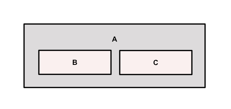
The following image shows a sample output rendering for the paths provided in the example mentioned above.

You can use archimate-diagram-engine to render Archimate views using JointJS
Output
The generated diagram is returned as a View, which is an object containing mainly the View Nodes and View Relationships. From this object, you can render your diagram using a drawing tool of your choice.
A View is structured as follows:
{
  id: string;
  viewRelationships: [
      {
          name: string;
          type: string;
          parentId: string | null;
          modelNodeId: string;
          viewNodeId: string;
      }
  ];
  viewNodes: [
      {
          modelRelationshipId: string;
          sourceId: string;
          targetId: string;
          viewRelationshipId: string;
          type: string;
          bendpoints: [{ x: number; y: number }];
      }
  ];
  name: string;
  bounds: {
    horizontal: { min: number; max: number };
    vertical: { min: number; max: number };
  };
}
Settings
You can control how the View will be generated by adjusting Settings parameters.
- layoutType LayoutTypes: Layout option. Currently, can be nested or hierarchy
- maxHorizontalCount number: How many elements are allowed on the same row at level 0 (root level)
- maxChildrenHorizontalCount number: How many children elements are allowed on the same row within the parent scope
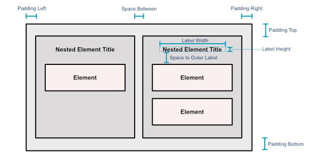
- spaceBetween number: Points between elements
- spaceToOuterLabel number: Points between the first element and the label area
- sizeUnit number: Small size unit to be used to build elements. An ordinary element has 3 Size Units (Width) x 1 Size Unit (Height)
- leftPadding number: Padding between nested elements and the parent's left border
- rightPadding number: Padding between nested elements and the parent's right border
- topPadding number: Padding between nested elements and the parent's top border
- bottomPadding number: Padding between nested elements and the parent's bottom border
- labelWidth number: Label area width
- labelHeight number: Label area height
- lateralLabel boolean: Indicates that the label area must be placed sideways
The image below illustrates how the Settings parameters affect the generated visualization.
