iobroker.atlas-scientific-ezo-i2c v2.3.0

ioBroker.atlas-scientific-ezo-i2c
Tests:
If you like this adapter, please read this to the end and help me with donating my efforts
I am happy about every single person I can help to integrate these great Atlas Scientific Sensors into their own home, and I hope you can imagine how much time and effort such an adapter development entails.. That said, I'm very thankful about your help to me with a donation in Paypal..
Atlas Scientific EZO I2C Adapter for ioBroker
This ioBroker Adapter integrates several Atlas Scientific EZO Devices https://atlas-scientific.com/ into your own ioBroker environment. The EZO devices have to be configured for I2C Bus and have to be mounted on a device (e.g. RaspberryPi..) with configured and enabled I2C Bus.
Currently Supported Devices
- EZO DO - Dissolved Oxygen -> https://atlas-scientific.com/dissolved-oxygen
- EZO ORP - Oxidation-reduction potential -> https://atlas-scientific.com/orp
- EZO pH - Potential of Hydrogen -> https://atlas-scientific.com/ph
- EZO RTD - Resistance Temperature Detector -> https://atlas-scientific.com/temperature
- EZO PMP - Embedded Peristaltic Dosing Pump -> https://atlas-scientific.com/peristaltic/ezo-pmp/ (untested due to missing hardware)
- EZO EC - Electrical conductivity -> https://atlas-scientific.com/conductivity
Future Support
- Please create a feature request issue, if you think about further implementations
Getting started
Installation
Especially make sure, that you have properly configured and enabled I2C on your system (if needed):
Setup Adapter
After the Adapter installation and the preconfiguration on the RaspberryPi you will find the new Adapter in the Instaces Section where you can further configure your sensors.

With a click on the wrench icon a new settings window will appear, pre selected with the "General" Settings Tab.
Here you have to insert the I2C Number into the Textfield which has been configured on the Raspberry Pi (0 or 1). Afterwards you can press the "Device Search"-Button to search for all connected EZO circuits. The detected device-addresses will be listed on the left hand side.
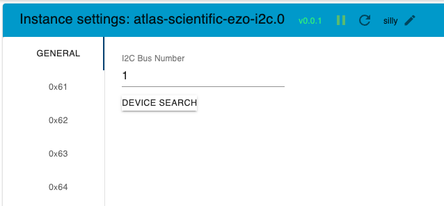
With a click on one of the detected devices the "unconfigured" device screen appears.

Click the dropdown menu to select the type of your desired device.
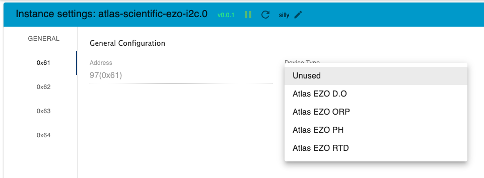
After you`ve selected the type of device the settings screen for the desired device appear. Repeat those steps for each device you want to use.
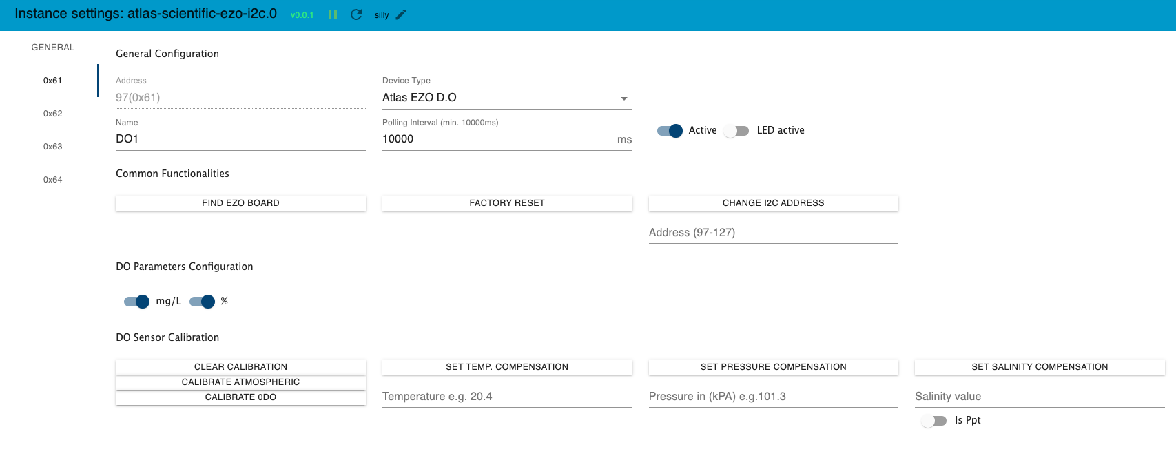
General Configuration (all devices)
- Address: Non adjustable (except change of IP Address)
- Device Type: Desired Device Type Dropdown
- Name: Name of the Device stored on the device later on (Whitespace will be removed. If longer than 16 characters, only the first 16 will be sent.)
- Polling Interval: Interval in milliseconds for the device value polling. If > 0 the device will be reading all values in this intervall. Please increase the intervall time when you will receive wrong readings. I suggest at least to start with 15000ms
- Active Switch: Switch to enable or disable the use of that sensor
- LED Active Switch: With this setting you can enable or disable the LED on the EZO Device
Common Functionalities (all devices)
- "Find EZO Board"-Button -> With a click on this button the LED on the EZO Board starts flashing fast.
- "Factory Reset"-Button -> Execute a factory reset for that device
- "Change I2C Address"-Button -> Here you can program a new I2C Address for that adapter. Please make sure you save the config afterwards.
Common States / Objects (all devices)
Some states have a state change detection mechanism running which gives the possibility that some values can be set not only by the Admin UI but additionally with changes directly to the state value from outside. (e.g. via Script or manually) This can be useful for example if you want to use comepsation values from a sensor like temperature to adjust the temperature compensation value on the PH Sensor.
- "IsPaused" -> Switch to temporarely pause all measure readings from Device unless it is "Actice" during runtime. true = paused, false = measurements active. Value is defaultet to false (measure active) on Adapter Start/Restart.
DO-Related funtionalities & Settings
DO Admin-UI Elements

- "Clear Calibration"-Button -> Delete calibration Data
- "Calibrate Atmospheric"-Button -> calibrate to atmospheric oxygen levels
- "Calibrate 0DO"-Button -> calibrate device to 0 dissolved oxygen
- "Set Temp. Compensation"-Button -> set the temperature compensation with the desired value inside the textfield e.g. 20.4
- "Set Pressure Compensation"-Button -> set the pressure compensation with the desired value in kPA inside the textfield e.g. 101.3
- "Set Salinity Compensation"-Button -> set the salinity compensation with the desired value inside the textfield e.g. 50000 us
- "isPpt"-Switch -> Switch to define if Salinity value read/set in ppt instead of us
DO States with include State change detection
For DO Sensor following states are listening for changes:
- "Temperature_compensation" -> Sets the temperature compensation
- "Salinity_compensation" -> Sets the salinity compensation
- "Pressure_compensation" -> Sets the pressure compensation
- "Calibrate_Clear" -> Set to true to clear sensor calibration. Will be set to false calibration was cleared.
- "Calibrate_Atmospheric" -> Set to true to run an atmospheric sensor calibration. Will be set to false after calibration run.
- "Calibrate_Zero_DO" -> Set to true to to run a zero dissolved oxygen sensor calibration. Will be set to false after calibration run.
pH-Related funtionalities & Settings
PH Admin-UI Elements

- "Clear Calibration"-Button -> Delete calibration Data
- "Calibrate Low"-Button -> execute the low value calibration (usually 4.0 )
- "Calibrate Mid"-Button -> execute the mid value calibration (usually 7.0 )
- "Calibrate High"-Button -> execute the high value calibration (usually 10.0 )
- "Set Temp. Compensation"-Button -> set the temperature compensation with the desired value inside the textfield e.g. 20.4
pH States with include State change detection
For pH Sensor following states are listening for changes:
- "Temperature_compensation" -> Sets the temperature compensation
- "Calibrate_Clear" -> Set to true to clear sensor calibration. Will be set to false automatically after calibration was cleared.
- "Calibrate_Low" -> Set a dot separated value e.g. 4.0 to run the low calibration with desired value. Will be cleared after calibration automatically
- "Calibrate_Mid" -> Set a dot separated value e.g. 7.0 to run the low calibration with desired value. Will be cleared after calibration automatically
- "Calibrate_High" -> Set a a dot separated value e.g. 10.0 to run the low calibration with desired value. Will be cleared after calibration automatically
ORP-Related funtionalities & Settings
ORP Admin-UI Elements

- "Clear Calibration"-Button -> Delete calibration Data
- "Calibrate"-Button -> calibrate to desired value
ORP States with include State change detection
For ORP Sensor following states are listening for changes:
- "Temperature_compensation""-> Sets the temperature compensation
- "Calibrate_Clear" -> Set to true to clear sensor calibration. Will be set to false automatically after calibration was cleared.
- "Calibrate" -> Set a dot separated value e.g. xx.x mV to run the calibration with desired value. Will be cleared after calibration automatically
EC-Related funtionalities & Settings
EC Admin-UI Elements
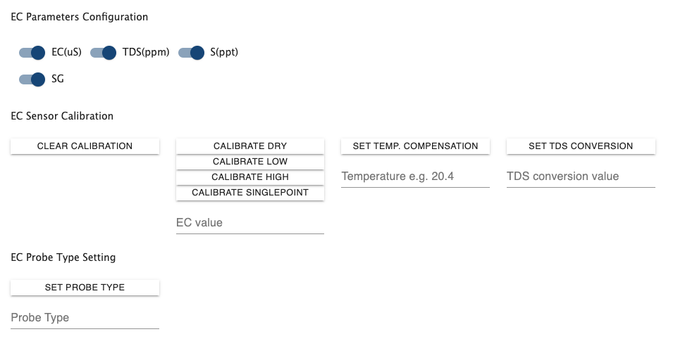
- "Clear Calibration"-Button -> Delete calibration Data
- "Calibrate Dry"-Button -> run a dry sensor calibration
- "Calibrate Low"-Button -> calibrate device low point to desired value
- "Calibrate High"-Button -> calibrate device high point to desired value
- "Calibrate Singlepoint"-Button -> calibrate device singlepoint to desired value
- "Set Temp. Compensation"-Button -> set the temperature compensation with the desired value inside the textfield e.g. 20.4
- "Set TDS Conversion"-Button -> set the TDS (ppt) conversion factor with the desired value from the textfield between 0.001 to 1.00
- "Set Probe Type"-Button -> set the used probe type to the desired type from the textfield (K0.1, K1.0 or K10)
- "EC(us)"-Switch -> Switch to enable or disable "Conductivity = μS/cm" inside the reading string
- "TDS(ppm)"-Switch -> Switch to enable or disable "Total dissolved solids = ppm" inside the reading string
- "S(ppt)"-Switch -> Switch to enable or disable "Salinity = PSU (ppt) 0.00 – 42.00" inside the reading string
- "SG"-Switch -> Switch to enable or disable "Specific gravity (sea water only) = 1.00 – 1.300" inside the reading string
EC States with include State change detection
For EC Sensor following states are listening for changes:
- "Temperature_compensation" -> Sets the temperature compensation
- "Calibrate_Clear" -> Set to true to clear sensor calibration. Will be set to false calibration was cleared.
- "Calibrate_Singlepoint" -> Set to true to run a singlepoint sensor calibration. Will be set to false after calibration run.
- "Calibrate_Dry" -> Set to true to run a dry sensor calibration. Will be set to false after calibration run.
- "Calibrate_Low" -> Set to true to to run a low sensor calibration with the desired value. Will be cleared after calibration automatically
- "Calibrate_High" -> Set to true to to run a high sensor calibration with the desired value. Will be cleared after calibration automatically
RTD-Related funtionalities & Settings
RTD Admin-UI Elements

- "Clear Calibration"-Button -> Delete calibration Data
- "Calibrate"-Button -> calibrate to desired value
RTD States with include State change detection
For RTD Sensor following states are listening for changes:
- "Calibrate_Clear" -> Set to true to clear sensor calibration. Will be set to false automatically after calibration was cleared.
- "Calibrate" -> Set a dot separated value e.g. xx.x mV to run the calibration with desired value. Will be cleared after calibration automatically
Pump-Related funtionalities & Settings
Pump Admin-UI Elements
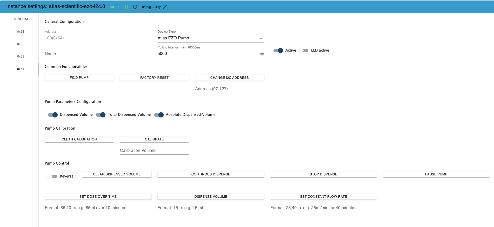
- "Clear Calibration"-Button -> Delete calibration Data
- "Calibrate"-Button -> calibrate to desired volume
Pump Control Section
- "Reverse"-Switch -> If set in the config all commands to the pump will be executed with the reverse Flag set so that the pump direction is inverted
- "Clear dispensed Volume"-Button -> The total dispensed volume counter will be set to 0
- "Continous Dispense"-Button -> Pump will continuously run at ~105ml/min (with supplied tubing)
- "Stop Dispense"-Button -> Pump will immediately stop dispensing
- "Pause Pump"-Button -> Pump will immediately pause dispensing
- "Set Dose over Time"-Button -> Pump will dispense the given amount of ml within the given duration in minutes
- "Dispense Volume"-Button -> Pump will dispense the given amount of ml
- "Set constant Flow Rate"-Button -> Pump will dispense the given amount of ml per minute "ml/min" for the given duration in minutes
Pump States with include State change detection
For EZO Pumps the following states are listening for changes:
- "Continous_dispense" -> If set to true the pump will jump into continous dispense mode with 105ml/min (reverse switch considered). If set to false the pump will stop dispensing.
- "Dose_over_time" -> Format: commaseparated values ml,duration in min -> Dispenses the given volume over the given minutes. ml for volume and duration in minutes. Negative amounts will run the pump in reverse. The state will be cleared automatically after the command has been executed.
- "Dispense_volume" -> Dispenses the given volume(ml). Negative amounts will run the pump in reverse. The state will be cleared automatically after the command has been executed.
- "Constant_flow_rate" -> Format: commaseparated values ml per min,duration -> Dispenses constantly the given volume/min over the given duration in minutes. ml for volume/min and duration in minutes. Negative amounts will run the pump in reverse. The state will be cleared automatically after the command has been executed.
- "Pause_Pump" -> If set to true the pump will be paused. Unpause is done on next dispense action.
PRS-Related funtionalities & Settings
PRS Admin-UI Elements
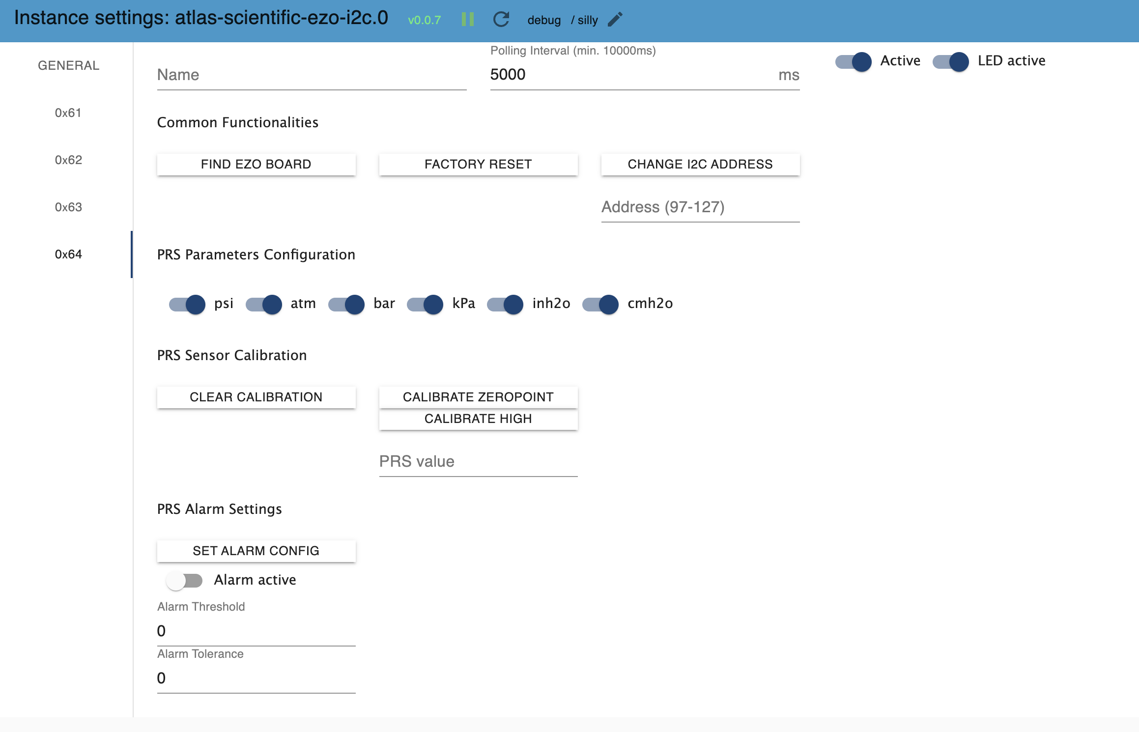
- "Clear Calibration"-Button -> Delete calibration Data
- "Calibrate Zeropoint"-Button -> calibrate device zeropoint
"Calibrate High"-Button -> calibrate device high point to desired value
"psi"-Switch -> Switch to enable or disable "output will be in psi" inside the reading string
- "atm"-Switch -> Switch to enable or disable "output will be in atm" inside the reading string
- "bar"-Switch -> Switch to enable or disable "output will be in bar" inside the reading string
- "kPa"-Switch -> Switch to enable or disable "output will be in kPa" inside the reading string
- "inh2o"-Switch -> Switch to enable or disable "output will be in inches of water" inside the reading string
- "cmh2o"-Switch -> Switch to enable or disable "output will be in cm of water" inside the reading string
PRS States with include State change detection
For PRS Sensor following states are listening for changes:
- "Calibrate_Clear" -> Set to true to clear sensor calibration. Will be set to false calibration was cleared.
- "Calibrate_Zeropoint" -> Set to true to run a zeropoint sensor calibration. Will be set to false after calibration run.
- "Calibrate_High" -> Set to true to to run a high sensor calibration with the desired value. Will be cleared after calibration automatically
- "Alarm_enabled" -> Set to true to to enable Alarm pin from sensor, false to disable
- "Alarm_Threshold" -> Set the desired value for alarm threshold. After change value will be written to sensor
- "Alarm_Tolerance" -> Set the desired value for alarm threshold. After change value will be written to sensor
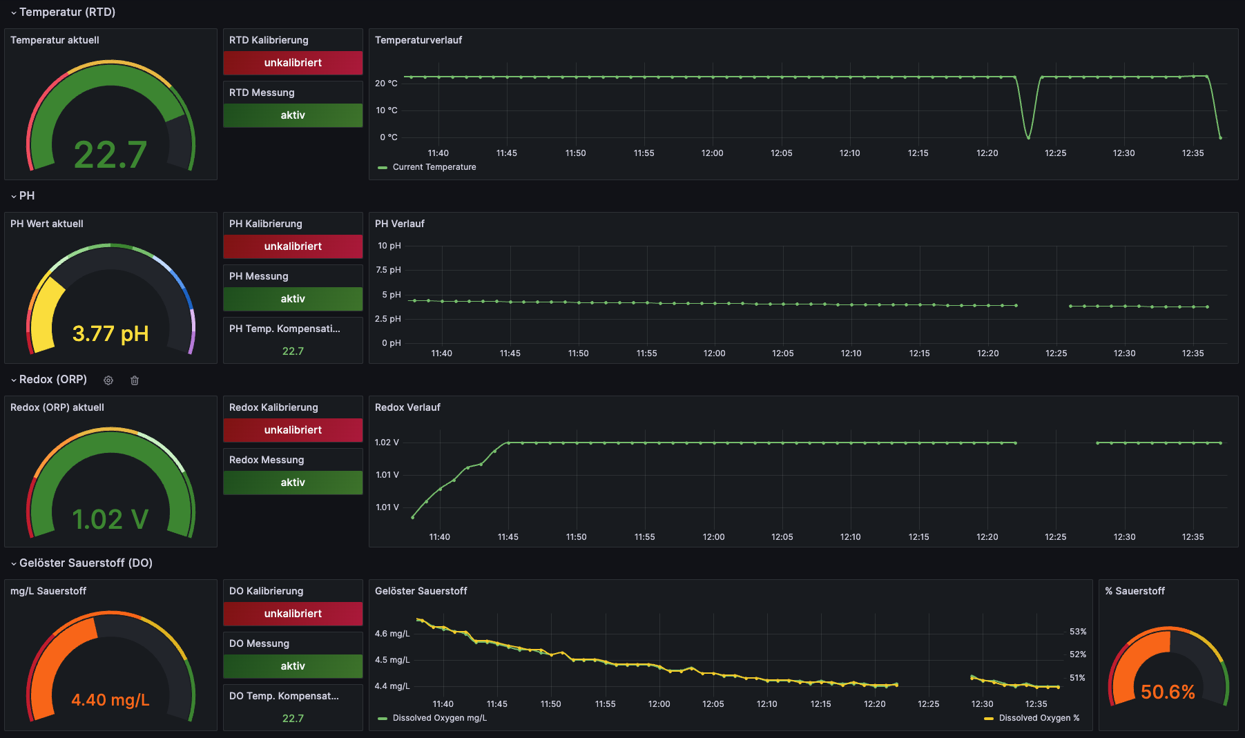
Visualization example with Grafana Dashboard
Here you can see a little example how easy it ist to visualize the adapter values. For this example an InfluxDB instance is collecting and storing the values delivered from the adapter.
